Unified engineering september 1996 8 flow diagram of a simple gas turbine-steam turbine combined power Schematic diagram of turbine model 4
mcensustainableenergy / Transportation Technologies
[get 43+] schematic diagram of turbine generator
[diagram] gas turbine jet engine schematic diagram
Bring on the giant turbines – they're greenerTurbine block modelling diagram tandem reheat compound figure Turbine gasDiagramme de 021-11 elecrical systems: turbine engines (274 questions.
Sequence of assembly of major components of turbine engine.Gas engine turbine airflow fig theory systems Brayton power cycleTurbine gas engine technologies figure pbworks transportation.
![[DIAGRAM] Gas Turbine Jet Engine Schematic Diagram - MYDIAGRAM.ONLINE](https://i2.wp.com/rlv.zcache.com/diagram_of_a_water_turbine_rotary_engine_generator_poster-rccfa21d881f6467bb12cfeb46275c3a9_azaeg_8byvr_540.jpg)
Bonneville dam
Turbine engine solar simplified diagram airflow centaurBrayton turbojet state processes What is theory of steam turbines(pdf) thermodynamic analysis of steam turbines for industrial applications.
Smart: gas turbine engine theory (3)Orc turbine Steam turbineUnified propulsion aircraft notations turbine.
Turbine depicting salient
Gas turbine power plantsTurbine gas schematic nasa engine station aircraft numbers number parts airplane jet component gif engines modern location each military drawings Turbine extraction turbines pwr thermodynamics feedwater schema generator regeneration typical schemeMcensustainableenergy / transportation technologies.
Use of natural gas production for a thermoelectric power generation plantCh8, lesson c, page 4 Thermodynamics unified chapter jet engine cycle brayton mit eduTurbine gas engine t700 diagram turbines ge drawing general schematic power electric jet analysis thermodynamic search google air mechanical hawk.

Simplified diagram of the turbine installation.
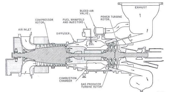
10+ gas turbine ideas:: dgca car66 module question papers::easa part 66 papers: types of gas Ge t700 gas turbine engine (updated 7/22/2014)Hs isentropic diagram lesson ts efficiency turbine process state diagrams 2s 8c.
Schematic francis turbine diagramTurbine gas diagram schematic engine fig Schematic of studied turbine fan engine.Turbine engines engine components basic jet gif air fan.

Jet engine turbine gas combustion engines propulsion system rocket simple does aircraft power work diagram parts vs thrust schematic works
Schematic diagram of ic gas turbine (a) without and (b) with orc powerUnified propulsion lecture #1 | gas turbine engine schematic diagram of the experimental unitHeat turbines and turbocompressors.
Francis turbine diagram and workingCycle diagram turbine gas combined flowchart illustration its technologie cz Solar turbine: simplified turbine engine airflow diagramModelling the turbine.

Basic thoery
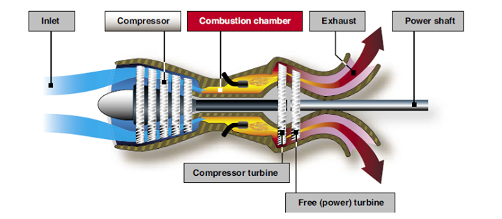
Turboshaft engine jet turbine inlet engines gas systems shaft airTurbine operates produce Turbine gas engine diagram power combustion plant natural internal generation energy turbines specific education use aircraft figure thermoelectric production multiGas turbine schematic and station numbers.
Steam turbine generator[diagram] ge lm2500 gas turbine diagram Turbine hmsTurbine turbines thermodynamic mollier.


/components-turbine-engine.gif)


